

Blog
Motor Positioning Examples for Real Applications

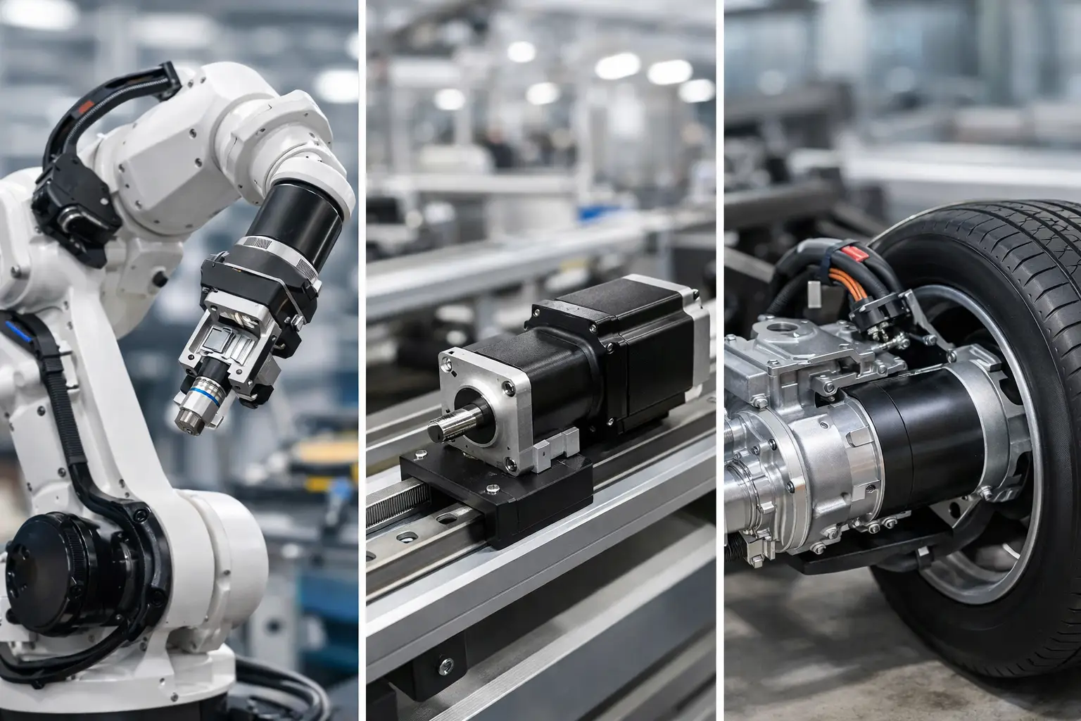
A motor that simply turns is easy to specify. A motor that must stop at exactly the right place, repeat that move thousands of times, and recover safely after an interruption is a positioning system. These motor positioning examples show how the application, load, required accuracy, and feedback method shape the final design.
What Motor Positioning Means
Motor positioning is the controlled movement of a shaft, wheel, belt, screw, or arm to a known location. That location may be an angle, such as a valve opening at 45 degrees, or a linear distance, such as a carriage traveling 18 inches down a rail.
The motor is only one part of the job. A useful system also has a controller, a way to measure movement, a mechanical transmission, and a reference position. In simpler equipment, a stepper motor and a limit switch may be enough. In faster or higher-consequence equipment, a servo motor with encoder feedback is often the better fit.
Accuracy, repeatability, and resolution are related but not identical. Accuracy is how close the machine reaches the commanded position. Repeatability is how consistently it returns to the same point. Resolution is the smallest movement the control system can command or detect. A machine can have fine resolution and still miss its true target because of backlash, belt stretch, slipping, or poor calibration.
Motor Positioning Examples in Equipment
Conveyor indexing at a packaging station
Consider a conveyor that moves trays through a filling or labeling station. The belt must advance one tray length, stop, allow the process to occur, and then advance again. This is called indexing.
For a light conveyor with consistent loads, a stepper motor driving a timing belt can work well. The controller commands a fixed number of steps per index, and a home sensor establishes the starting position when the machine powers up. This approach is straightforward and cost-conscious, but it assumes the motor does not lose steps.
A servo system is a stronger choice when trays vary in weight, acceleration must be high, or the position must be verified at every cycle. The encoder reports actual shaft motion to the controller. If the conveyor encounters an obstruction or its load changes, the control system can detect following error rather than silently producing misplaced packages.
The common mistake is selecting a motor based only on the tray weight. The engineer also needs to account for belt inertia, gearbox ratio, desired cycle time, friction, and stopping distance. A conveyor that reaches position accurately but overshoots under real production speed is not properly sized.
Rotary valve and damper control
Many mechanical systems need a rotary actuator to place a valve, damper, or throttle at a specific angle. A ventilation damper may move from closed to fully open. A process valve may require several precise intermediate positions to control flow.
Here, the most practical feedback device is often an absolute encoder or a position sensor mounted at the output shaft. Measuring at the output matters because gearbox backlash can make motor-shaft feedback look more accurate than the valve actually is. If the gearbox has noticeable play, approaching each target from the same direction can also improve repeatability.
Not every valve needs servo-level precision. For open-close service, two limit switches may be all that is necessary. For proportional flow control, the system needs a calibrated relationship between shaft angle and actual flow. Those are different requirements, and the motor should be selected accordingly.
Pick-and-place robot arm movement
A pick-and-place arm shows why positioning is about more than reaching a coordinate. The arm must move quickly, avoid vibration, place a part gently, and return for the next cycle. A servo motor paired with a low-backlash reducer is common because the controller must manage acceleration and deceleration as carefully as final position.
The arm’s effective load changes as it extends. A motor that works at the home position can struggle when the arm is fully extended, since torque demand rises with distance from the pivot. Payload weight, arm weight, center of gravity, and the desired move time all belong in the calculation.
Closed-loop feedback helps the robot correct for load changes, but it cannot eliminate mechanical problems. Flexing brackets, loose couplings, worn reducers, and an undersized frame can create oscillation at the tool. The best motion profile will not compensate for a weak mechanical structure.
Camera pan, tilt, and focus mechanisms
Positioning systems are also common in inspection cameras, security mounts, and automated imaging equipment. A pan-tilt unit may need to return to the same viewing angle after a sweep, while a focus mechanism may move a lens in tiny increments.
Low noise and smoothness matter here. A stepper motor can provide high incremental control, particularly at low speeds, but it may create vibration or audible resonance. Microstepping can reduce this effect, although it does not automatically guarantee proportional mechanical movement under every load condition.
For precision imaging, designers often use encoders, fine-pitch lead screws, or direct-drive arrangements. A direct drive removes some backlash-producing parts, but it may cost more and demand a larger motor to provide the needed torque. The right choice depends on whether the priority is cost, compact size, quiet operation, or repeatable focus.
Vehicle seat, mirror, and steering adjustments
Automotive-style positioning applications frequently use small DC motors with gearboxes and feedback devices. A powered seat may save several user settings. The controller needs to know not only whether the seat is moving, but where each axis is located: forward-back, height, recline, and lumbar adjustment.
Hall-effect sensors can count motor rotation, while potentiometers or position sensors can report a mechanism’s location. End stops remain valuable as a safety boundary, especially when a sensor signal is lost or an initial calibration has not completed.
These applications highlight a practical trade-off. A highly precise feedback system may be unnecessary if the user only needs a comfortable, repeatable setting within a small tolerance. Yet the mechanism must still tolerate stalls, obstruction, temperature changes, and long-term gear wear. Reliability often matters more than extremely fine resolution.
Linear actuator positioning for gates and panels
A motor-driven linear actuator can open a gate, raise a panel, adjust a work surface, or move a protective guard. The motor usually turns a lead screw, ball screw, rack, or belt that converts rotation into linear travel.
A basic actuator may use retracted and extended limit switches. More capable systems use an encoder to stop at multiple intermediate points, such as partially opening a gate or setting a panel to a programmed height. If people can be near the moving equipment, force sensing, current monitoring, or obstruction detection should be part of the design.
Lead screws are often economical and can hold a load when stopped, but speed may be limited. Belt drives can move quickly over longer distances but may stretch and require tension maintenance. Ball screws offer efficiency and precision, although they generally cost more and need protection from contamination. The mechanism is as significant as the motor itself.
Choosing Feedback for the Positioning Task
Open-loop control means the controller commands motor movement without confirming that the load reached the target. Stepper systems are the most familiar example. They can be effective for predictable, lightly loaded machines, particularly when a home switch resets the system at startup. Their main weakness is that a missed step may go unnoticed.
Closed-loop control uses a sensor to compare commanded position with actual position. Incremental encoders measure movement from a known reference point. Absolute encoders retain or report a unique position value, which can simplify recovery after a power cycle. Resolver-based feedback is also used where heat, vibration, or electrical noise makes ordinary encoder operation less suitable.
Feedback should be located where errors matter. If belt stretch, a flexible shaft, or gearbox backlash can occur between the motor and the load, motor-mounted feedback only tells part of the story. Load-side measurement gives a truer result, though it adds complexity and cost.
Practical Checks Before Specifying a Motor
Before selecting a motor and drive, define the required travel, final position tolerance, repeatability, cycle time, load inertia, and duty cycle. Also define what happens when power is lost. Some systems can re-home slowly when restarted. Others, such as a safety gate or a multi-axis machine, may need retained position information and a controlled recovery process.
Do not overlook acceleration. A motor may have adequate holding torque yet fail to accelerate the load fast enough for the required cycle. Likewise, a system may reach speed but create damaging shock at the stop if deceleration is too abrupt. Motion profiles with gradual acceleration and deceleration often improve both accuracy and mechanical life.
Environmental conditions can change the answer. Dust affects screws and sensors. Moisture influences connector and enclosure choices. High temperatures reduce available motor performance. Electrical noise can corrupt encoder signals if wiring, grounding, and shielding are handled poorly. A positioning design that works on a clean test bench may need additional protection in the field.
The most useful starting point is not a motor part number. It is a clear definition of where the load must go, how often it must get there, and what failure looks like if it does not. From there, the right combination of motor, feedback, mechanics, and control becomes much easier to identify.